

Abstract
In the present work the behavior of a monochromatic electromagnetic wave propagating along the interface between dielectric and metallic media was rigorously studied. The exact analytical expressions of the electric and magnetic fields were derived. On the basis of the experimental data of the frequency dependent optical parameters of the media the dispersion and the attenuation of the surface plasmon polariton were determined by means of the numerical calculations
Export citation and abstract BibTeX RIS

Original content from this work may be used under the terms of the Creative Commons Attribution 3.0 licence. Any further distribution of this work must maintain attribution to the author(s) and the title of the work, journal citation and DOI.
1. Introduction
The fundamental and applied studies on the effects of the plasmon resonance in the electron gas of metal as well as of the large variety of related physical phenomena have led to the emergence of a new scientific area in photonics: plasmonics. The plasmon resonance propagating along the interface between a metallic and dielectric media is called the surface plasmon polariton (SPP). The highly successful theoretical and experimental researches on SPP have led to the rapid development of photonic technologies resulting in the creation of surface plasmon subwavelength optics [1] with the fabrication and exploitation of miniaturized photonic circuits and new types of photonic devices for data storage, optical elements for light generation, focusing, refraction and total internal reflection [2], surface plasmon waveguides [3–6] etc.
The theory of SPP in the interface between a metal and a dielectric was briefly presented in [7]. In particular, the spatial and temporal dependence of the monochromatic oscillating electromagnetic field at this interface was discussed in the simple case of the electron gas in the metal described by the Drude model. The dispersion curves in the case of the silver/air and silver/silica interface with the values of the frequency dependent complex dielectric constant determined from the experimental data on the index of refraction n and absorption coefficient k of Johnson and Christy [8] were also plotted in [7] without presenting the calculation method. However, for the theoretical study of plasmonic phenomena and processes related to the SPP it is necessary to use the explicit analytical formulae expressing the dispersion of the electromagnetic field at the interface. The derivation of the expressions analytically determining the dispersion of the electromagnetic field of the SPP is the purpose of the present work. On the basis of the analytical formulae determining the electric and magnetic fields, the propagation of the electromagnetic waves along the metal–dielectric interface and their attenuation will be investigated in detail.
2. Formulation of the problem and basic equation
The subject of the present work is the study of the propagation of a monochromatic wave at the plane interface between two non-magnetic isotropic homogeneous media, one being a dielectric medium with the (frequency independent) positive dielectric constant  > 0, another being a medium with (frequency independent) complex dielectric function
  ,
,  . We denote
For a monochromatic electromagnetic wave the electric field E(r,t), magnetic field H(r,t) and electric induction vector D(r,t) can be presented in the form


For the definiteness we chose the axis Oz to be perpendicular to the interface between two media such that the upper half-space is the dielectric medium and the lower half-space is the metallic one (figure 1). Then between electric field E(r,t) and electric induction vector D(r,t) there exists the following relation

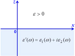
Figure 1. Dielectric medium (upper half-space) and metallic one (lower half-space).
Download figure:
Standard image High-resolution imageThe vector fields E(r), H(r) and D(r) must satisfy the system of Maxwell equations


where c is the light velocity in vacuum. From the system of equations (6)–(9) it follows the d'Alembert equation for the vector fields E(r) and H(r), for example

In this work we consider the electromagnetic fields of a special form: the electric and the magnetic fields E(x, y, z) and H(x, y, z) are independent of y and describe the electromagnetic wave propagating along axis Ox with the wave vector k:
Then we have
and the system of Maxwell equations becomes

Using the Ostrogradski–Gauss and Stoke theorems, from the Maxwell equations (13a )–(14c ) we derive following boundary condition at the interface:


They mean that the tangential components of the electric and magnetic fields as well as the normal components of the electric induction vector must be continuous across the interface. Maxwell equations in the form similar to equations (13a )–(14c ) and the boundary conditions (15)–(17) have been used previously in [7]. We must use these formulae in our subsequent calculations for deriving exact expressions of the solution of the Maxwell equations and therefore here we rewrite them for convenience in the presentation of our reasoning.
3. Exact expressions of the transverse solution
The solution of Maxwell equations (13a
)–(14c
) with the boundary conditions (15)–(17) with the y-independent electric and magnetic fields E(r) and H(r) of the form (11) can be considered as a vector field in the coordinate plane xOz. It is called the transverse magnetic solution if the magnetic field  is perpendicular to the plane xOz and therefore has only transverse component parallel to the axis Oy:

Similarly, it would be called the transverse electric solution if the electric field  is perpendicular to the plane xOz and therefore would have only the transverse component parallel to the axis Oy:

Below we shall see that there exists only transverse magnetic solution satisfying condition (18).
Consider now this transverse magnetic solution. From condition (18) and equation (14b ) it follows immediately that

We want to find the non-vanishing component  of the magnetic field in the form

Using equation (14a ) we obtain
Similarly, from equation (14c ) it follows that
Expression (23) for  satisfies the boundary condition (16). From the boundary condition (15) for
  it follows the equality

According to the d'Alembert equation (10) for both electric and magnetic fields E(r) and H(r) three parameters p,  and k must satisfy following two equations:


From these equations we obtain the formula

which was derived in [7].
We set

Since is real but  is complex ξ(ω) must be a complex function of ω:
It can be shown that


where


Since the electromagnetic wave propagating along the Ox axis can attenuate but cannot augment in the propagation process, the real part ξ1(ω) and imaginary part ξ2(ω) must satisfy condition

Formulaes (30a ), (30b ) and condition (33) determine the phase velocity of the electromagnetic wave propagating along the Ox axis and the special size of the wave packet, called also the propagation length [1].
The behavior of the electric and magnetic fields in the direction perpendicular to the interface, i.e. their z-dependence, is determined by two complex parameters p (in the half-space z > 0) and  (in the half-space z < 0). Introduce notations


Solving equations (25) and (26), we obtain following result:


Because the electromagnetic field must vanish at  , real part
  and
and  of p and
  must satisfy conditions

Similarly, the surface wave propagating along the Ox axis must attenuate, real part k1 and imaginary part k2 of k must satisfy conditions

Moreover, from equations (25) and (26) it follows that


Formulae (36)–(41) together with formulae (27)–(32) and conditions (42)–(45) completely determine the ω-dependence of p and  .
.
Now we consider the transverse electric solution defined by the condition (19)

From equation (14c ) it follows that

We want to find the non-vanishing component  of the electric field in the form

Then equation (13c ) gives
Similarly equation (13a ) gives

From expression (49) for Hx (0,0,z) and the boundary condition (17) we derive the equality

Because the electromagnetic field must vanish at  , real part
  and
and  must satisfy conditions (42). The contradiction between the equality (50) and conditions (42) means that the transverse electric solution does not exist, as was shown in [7].
4. Dispersion curves
From the above presented exact expressions of the real and imaginary parts of the complex parameters k, p,  and the frequency dependent values
  and
and  of the complex dielectric function
  of gold determined from the experimental data of Johnson and Christy [8] on the index of refraction n and the absorption coefficient k as well as the values of the dielectric constants of air ( = 1), silica ( = 2.25) and titania ( = 6.45) we can calculate immediately the frequency dependence of k1 and k2, p1 and p2,
  and
and  . Corresponding dispersion curves are plotted in figures 2(a) and (b) for k1 and k2, figures 3(a) and (b) for p1 and p2 and figures 4(a) and (b) for
  and
and  .
.
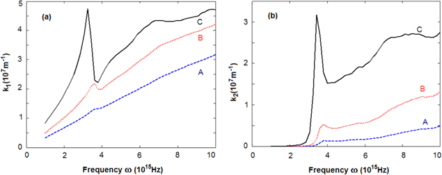
Figure 2. Frequency dependence of (a) real part k1 and (b) imaginary part k2 of the wave vector of SPP at the interface air/gold (A), silica/gold (B) and titania/gold (C) calculated by using experimental data on n and k in [8].
Download figure:
Standard image High-resolution image
Figure 3. Frequency dependence of the parameters (a) p1 and (b) p2 of SPP at the interface air/gold (A), silica/gold (B) and titania/gold (C) calculated by using experimental data on n and k in [8].
Download figure:
Standard image High-resolution image
Figure 4. Frequency dependence of the parameters (a)  and (b)
  of SPP at the interface air/gold (A), silica/gold (B) and titania/gold (C) calculated by using experimental data on n and k in [8].
Download figure:
Standard image High-resolution imageThe dispersion curves plotted in the above presented figures show that the magnitudes as well as the behaviours of the characteristic parameters of SPP strongly depend on the values of the dielectric constants of the dielectric media. For example, according to the results presented in figure 2(a), the frequency dependence of k1 for the SPP at the air/gold interface is almost linear, but in the case of the silica/gold interface there is a visible deviation from the linear frequency dependence near the frequency of 4 × 10¹⁵ Hz. Moreover, a very strong deviation from the linear frequency dependence in the region of frequencies larger than 2.5 × 10¹⁵ Hz takes place in the case of the titania/gold. For the comparison in the figures 5(a)–(c) we plot simultaneously the dispersion curves of k1 and straight lines representing the dispersion of the light in corresponding dielectric media.
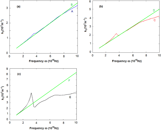
Figure 5. Dispersion curve of k1 of SPP (a) at air/gold interface (A) and the straight line (B) representing the dispersion of the light in air; (b) at the silica/gold interface (C) and the straight line (D) representing the dispersion of the light in silica; (c) at the at titania/gold interface (E) and the straight line (F) representing the dispersion of the light in titania.
Download figure:
Standard image High-resolution imageSince the propagation length L of SPP is inversely proportional to the imaginary part of k2

the cures plotted in figure 2(b) show that the propagation length of SPP at titania/gold interface is much shorter than that of SPP with the same frequency at silica/gold interface and the latter is again shorter than that of SPP with the same frequency at air/gold interface. A similar conclusion holds also for the depth

of the penetration of SPP from the interface into the dielectric medium. However, the dependence of the depth

of the penetration of SPP from the interface into the metal (gold) on the frequency as well as the dielectric constant of the dielectric is more complicated, as can be seen in figure 4(a).
For the comparison let us consider the special case, when the dielectric function  of gold is presented by the Drude formula

We must fit the expressions of the real part

and the imaginary part

with their values determined from the experimental data in [8]. Unfortunately, the fit for  can be done only in the frequency range ω < 2.5 × 10¹⁵ Hz, as this can be seen in figures 6(a) and (b). The obtained values of the parameter are
  = 9.84,
  = 13.8 × 10¹⁵ Hz,
  = 1.017 × 10¹⁴ Hz.
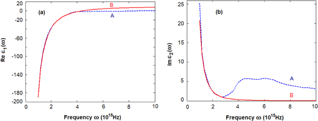
Figure 6. Frequency dependence of (a) real part 1(ω) and (b) imaginary part 2(ω) of the dielectric function of gold derived from the experiment of [8] (A) and calculated by using Drude formula (B).
Download figure:
Standard image High-resolution imageUsing Drude formula for the dielectric function  we have calculated the physical characteristic parameters of SPP. The results are represented by the dispersion curves plotted in figures 7(a) and (b) for k1 and k2, figures 8(a) and (b) for p1 and p2 and figures 9(a) and (b) for
  and
and  .
.
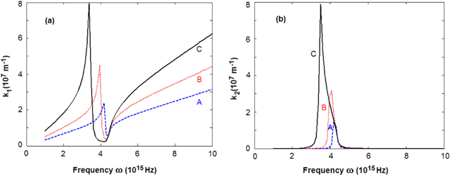
Figure 7. Frequency dependence of (a) real part k1 and (b) imaginary part k2 of the wave vector of SPP at the interface air/gold (A), silica/gold (B) and titania/gold (C) calculated by using formula Drude for the dielectric function.
Download figure:
Standard image High-resolution image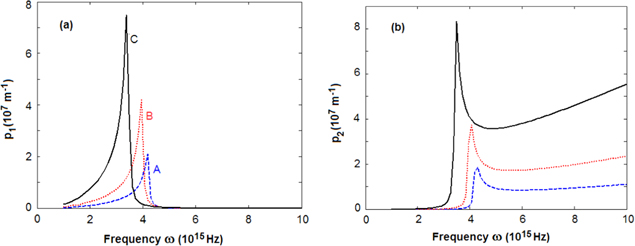
Figure 8. Frequency dependence of the parameters (a) real part p1 and (b) imaginary part p2 of SPP at the interface air/gold (A), silica/gold (B) and titania/gold (C) calculated by using formula Drude for the dielectric function.
Download figure:
Standard image High-resolution image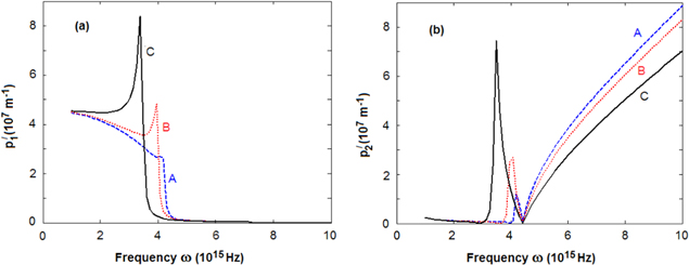
Figure 9. Frequency dependence of the parameters (a)  and (b)
  of SPP at the interface air/gold (A), silica/gold (B) and titania/gold (C) calculated by using formula Drude for the dielectric function.
Download figure:
Standard image High-resolution imageFor the comparison in figure 10 we plot simultaneously the dispersion curves of k1 and the straight lines representing the dispersion of the light in corresponding dielectric media.
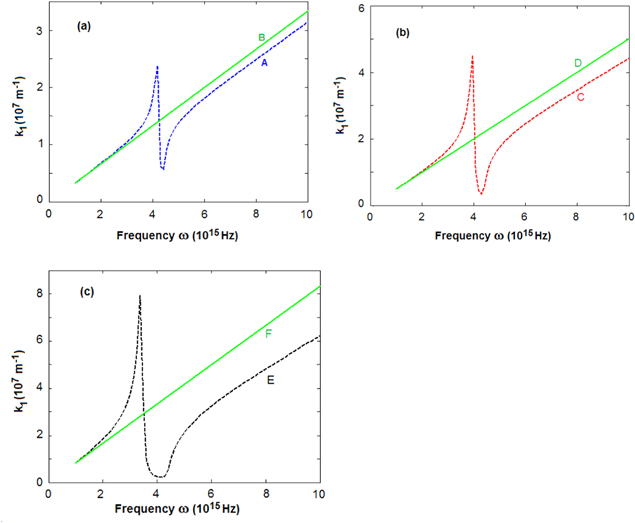
Figure 10. Dispersion curves of k1 of SPP (a) at air/gold interface (A) calculated by using Drude formula and the straight line (B) representing the dispersion of the light in air; (b) at the silica/gold interface (C) calculated by using Drude formula and the straight line (D) representing the dispersion of the light in silica; (c) at the titania/gold interface (E) calculated by using Drude formula and the straight line (F) representing the dispersion of the light in titania.
Download figure:
Standard image High-resolution image5. Conclusion and discussion
In this work we have performed a comprehensive study complementary to the previously published results [7] on the classical theory of SPP based on the use of Maxwell equations in material media and the boundary conditions at the interface without free charge between a dielectric medium and a metal. We have derived exact formulae expressing all six dynamic characteristic parameters of the electromagnetic wave propagating along this interface in terms of the dielectric constant of the dielectric medium, and the real and imaginary parts 1(ω) and 2(ω) of the complex dielectric functions (ω) of the metal.
Using derived exact formulae and the values of 1(ω) and 2(ω) derived from the experimental data on the refractive index and the absorption coefficient of the metal as well as the given value of the dielectric constant of the dielectric, we have calculated numerically the frequency dependent values of the physical characteristic parameters of SPP. The obtained results show that there is the significant deviation of the dispersion of the real part k1 of the wave vector of SPP from that of the wave vector of the light in the dielectric medium if the dielectric constant of this medium is much larger than 1. This is the case of the titania/gold interface.
For comparison we have calculated the values of the physical characteristic parameters of SPP using Drude formula of the complex dielectric function  of metal and always obtain the deviation from the dispersion lines of the light in dielectric in the frequency region where there exists the discrepancy between the values of 2(ω) determined by the Drude formula and those derived from the experimental data in [8].
The fast and large fluctuating variations of the values of dynamical characteristic parameters, in particular of the real part k1 of the wave vector of the SPP propagation along the interface, can take place according to two mechanisms:
- -very small values of the imaginary part2(ω) of the complex dielectric function
 of the metal;
 - -cancellation of the positive value of the dielectric constant of the dielectric and the negative values of the real part 1(ω) of the complex dielectric function of the metal.


Since in the Drude free electron theory the imaginary part 2(ω) is nearly vanishing at the frequency region w > 2.5 × 10¹⁵ Hz, the variation of the parameters (in this region) in the case of the Drude model is more significant in comparison with the case when large values of 2(ω) are derived from the experimental data of [8]. Besides, because the large positive value of the dielectric constant of titania is comparable with the absolute values of the negative real part 1(ω) of the complex dielectric function  and nearly cancels 1(ω), the variation of many parameters of SPP at the titania/gold interface is larger than those of other interfaces. Similarly, the variation of many parameters of SPP at the air/gold interface is the smallest one in comparison with other interfaces because the dielectric constant of air has the smallest value.
The new results presented above show that the exact expression of the dynamical characteristic parameter of SPP are very useful.
Acknowledgments
The authors would like to express their gratitude to Academician Nguyen Van Hieu for suggesting this problem and for the encouragement, and to Vietnam Academy of Science and Technology and Institute of Materials Science for the support.