

Abstract
We present novel resonant modes at the THz regime in a structure combining conventional metamaterial absorber (MA) with a cavity (MAC). The well-known structure consisting of three individual layers of periodic metallic dishes on the top, a dielectric layer in the middle, and a metallic film in the bottom is used, and the cavity is formed on the top layer by changing the geometry of the metallic dishes. MACs with various cavity parameters are designed and their absorption characteristics, such as magnetic field distribution, surface current, and power loss density at resonant frequencies of the designed structure, are numerically investigated. Resonant effects in this work may find applications in THz tunable and broadband MA, and our investigation on the dependence of the absorption frequency and absorption intensity on the geometric cavity of the designed structure will provide a general guideline for MAC design.
Export citation and abstract BibTeX RIS

Original content from this work may be used under the terms of the Creative Commons Attribution 3.0 licence. Any further distribution of this work must maintain attribution to the author(s) and the title of the work, journal citation and DOI.
1. Introduction
In 2000, metamaterials (MMs), a new class of artificial materials, was proposed by Smith et al [1] based on the idea of simultaneous negative permittivity and negative permeability. MMs allow one to create negative refraction in a frequency regime, which is also called left-handed medium (LHM) [1–3]. MMs can be used to manipulate electromagnetic waves due to their designed structure of shape, geometry, orientation, and constituent arrangement [4]. Numerous fascinating applications of MMs have been demonstrated such as superlenses [5] and invisible cloaking [6]. However, MM capability is not limited to directing electromagnetic waves. In 2008, Landy et al [7] firstly designed a thin metamaterial absorber (MA) structure, which is able to perfectly absorb electromagnetic waves at a certain frequency by matching impedance to the air and simultaneously inducing a high-loss medium. Magnetic and electric responses are conformed to eliminate all the propagations including reflection and transmission. The MA then has been rapidly improving with a lot of topics spreading on structure optimization, broadband operation and tunable properties to cater for promising realistic applications such as emitters [8], sensors [9], IR camouflage [10] and solar cell enhancement [11, 12]. Despite a huge number of studies, the absorption mechanism of MA is mainly interpreted as a result of either electromagnetic resonance [7, 13] or wave interference destruction [14].
The idea of merging the extraordinary properties of plasmonics and metamaterials has been proposed and improved by coupling waveguides and cavities inside MMs at deep subwavelength scale to manipulate the wave propagation [15, 16]. Pitchappa et al observed a new absorption behavior in the cavity of complementary MM in the near infrared region with absorption peak is ∼80% [17]. However, absorption behavior was not clarified and the efficiency did not reach to unity.
Recently, we presented the perfect absorption (PA) at GHz frequency of the MA of periodic metallic dishes [18]. The PA peak was demonstrated by optimizing the structural parameters. Multi-peak and broadband high absorption were achieved by manipulating the resonators in the metallic dish layer. In this work, we propose an alternative design in which the cavity induced PA of MM by changing the geometry of the metallic dishes. The structural parameters of the metamaterial absorber with cavity (MAC) are chosen for frequency of operation at THz regime, in which the plasmon effect may be more attractive than at GHz regime. The numerical results of magnetic field distribution, surface current, and power loss density at resonant frequencies of the MAC, were examined to understanding the mechanism of the resonant effects which induced PA in MMs. Looking at magnetic field distribution and power loss density, the confining electromagnetic wave at the cavity position is observed in the MAC. Furthermore, we also investigate the dependence of the absorption frequency and absorption intensity on the geometric cavity of the designed structure to assess the absorption performance. Our presented work has shown that the MAC is able to maintain the THz tunable and broadband MMs with various structural parameters.
2. Design and simulation
Figure 1(a) shows schematic diagram of MAC of metallic dishes. Based on our previous work [18], the conventional MA was designed including three layers: (i) the top layer consists of nine dishes of gold with a radius R = 2.7 μm and thickness tm = 0.1 μm in each unit cell, the middle layer is polyimide with thickness td = 0.8 μm, and the bottom layer is a gold film with thickness tm covering the whole area. A MAC model was created from conventional MA by missing the center dish and/or shipping the four disks along the polarization axes.
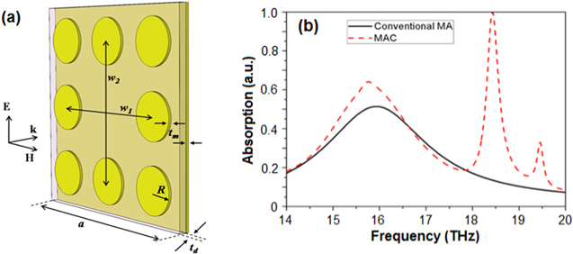
Figure 1. (a) Schematic diagram of MAC structure of metallic dishes (by missing the dish center from conventional MA) with incident electromagnetic wave polarization and (b) Simulated absorption spectra of conventional MA (solid black line) and MAC (dashed red line) models.
Download figure:
Standard image High-resolution imageNumerical results were obtained by using commercial CST Microwave Studio. Two ports were placed in front of and behind MAs and MACs to simulate wave-matter interaction and to export S parameters as the results. Then, the absorption is calculated through formula A(w) = 1 − R(w) − T(w) = 1 − |S11|2 − |S21|2, where R(w) = |S11|2 and R(w) = |S21|2 are reflection and transmission, respectively. Other interaction phenomena such as surface current, power distribution, and magnetic energy distribution which are not facile to observe experimentally are also performed.
3. Results and discussion
3.1. Cavity induced perfect absorption
The cavity has ability to confine electromagnetic waves and increase energy density at resonant frequency [19]. Therefore, we create a cavity in a conventional MA to trap electromagnetic waves and dissipate them through the local resonator. Likely to conventional point of view on perfect absorption in MA, we simultaneously reduce the reflectance component by matching the impedance between the propagation media (air and MA) and eliminate the transmission component by placing a fully-covered metallic plate behind the MA. Thus, the absorption is now calculated by A(w) = 1 − R(w) = 1 − |S11|2. Figure 1(b) shows simulated absorption spectra of conventional MA and MAC models corresponding to solid (black) and dashed (red) lines in the frequency regime from 14 to 20 THz. We can clearly see an absorption peak at 15.77 THz in both cases of conventional MA and MAC models, and absorption intensity of MAC model increases to 65% compared to conventional MA model as 50%. For MAC model, the perfect absorption peak is observed at 18.43 THz and another weak absorption peak at 19.5 THz.
The physical origin of the observation can be explained by the interaction between electromagnetic wave and MA that is indicated through magnetic field distribution. Figures 2(a) and (b) show the magnetic field distributions in cavity model corresponding to the absorption peaks at 15.77 THz and 18.43 THz, respectively. At the frequency of 15.77 THz (figure 2(a)), magnetic field concentrates at the four dishes around the cavity, which is different with uniform distribution of location at all the dishes in the case of a conventional MA model [18]. While, for the frequency of 18.43 THz (figure 2(b)), magnetic field mostly concentrates at cavity position, briefly at the corners and rarely at the four dishes around the cavity which is inverse to the previous case. This can be explained by the current distribution of MA.
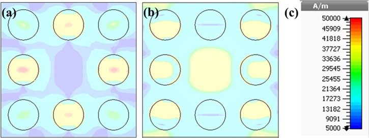
Figure 2. Magnetic field distribution in the MA at 15.77 THz (a) and 18.43 THz (b) with scale (c).
Download figure:
Standard image High-resolution imageFigure 3 shows surface current distribution on the top dish and bottom metallic layers at 15.77 THz and 18.43 THz. At the frequency of 15.77 THz in figures 3(a) and (b), the anti-parallel currents appear at the dish positions, and no electric current occurs at the cavity position. It is similar to a conventional MA model, in that PA is formed from magnetic resonance between the top and the bottom layer [18, 20, 21]. However, at the frequency of 18.43 THz in figures 3(c) and (d), the anti- parallel currents are not only observed at the position of dishes, but also the strong currents appear at the cavity position on the bottom metallic layer. The currents at the cavity position as shown in figure 3(d) agree and associate with the distribution of magnetic field at there in figure 2(b). The observed results indicate that the PA peak at 18.43 THz is caused by cavity resonance.

Figure 3. Surface current distributions on the top dish (a), (c) and bottom metallic (b), (d) layers at 15.77 THz (a, b) and 18.43 THz (c), (d), respectively.
Download figure:
Standard image High-resolution imageTo understand what causes power losses in the cavity model, we calculated power loss density on three layers of the MA structure. Figures 4(a)–(c) show power loss densities on the top dish, middle dielectric, and bottom metallic layers at 15.77 THz, respectively. Similarly, figures 4(e)–(g) show power loss density on the top dish, middle dielectric, and bottom metallic layers at 18.43 THz, respectively. As shown in both frequencies, energy dissipation occurs mainly on the bottom metallic layer, and a part of energy is distributed on the middle dielectric layer. However, the distribution of energy density is quite different between 15.77 THz (figure 4(c)) and 18.43 THz (figure 4(g)). At the frequency of 15.77 THz (figure 4(c)), energy loss is observed at the four dishes around the cavity, and no loss can be seen at the cavity position.

Figure 4. Power loss density on the top dish (a), (e), middle dielectric (b), (f), bottom metallic layers (c), (g), and scale bar (d), (h) at 15.77 THz (a)–(d) and 18.43 THz (e)–(h), respectively.
Download figure:
Standard image High-resolution imageAt the frequency of 18.43 THz (figure 4(g)), the strongest loss occurs at the cavity position and in other dishes at the corners. These results are good agreement with magnetic field distribution in the MA structure, and PA caused by magnetic resonance [18]. The induced current at cavity position on the metallic layer plays a key role in PA of electromagnetic wave.
3.2. Influences of structural parameters
Structural parameters always play a significant role in performance of the extraordinary properties of MMs such as magnetic resonance [22], left-handed behavior [23], or electromagnetic wave perfect absorption without reflection [24]. In this work, the parameters of the cavity in MAC were changed to investigate its resonant frequency and absorption intensity, but periodicity is kept constant (a = 24 μm). Figures 5(a) and (b) show the dependence of resonant frequency and absorption intensity on the cavity size corresponding to the H-field and E-field directions of the incident wave, respectively. The distance between the dishes on the right and the left of the cavity (H-field direction) is called w1 and the distance between the dishes above and below the cavity (E-field direction) is called w2 as shown in figure 1.
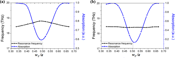
Figure 5. Dependence of resonant frequency (circles, black) and absorption intensity (squares, blue) on the variation of w1 (a) and w2 (b).
Download figure:
Standard image High-resolution imageAs shown in figure 5(a), when w1 decreases from 16 μm to 8 μm, the resonant frequency slightly shifts from 18.43 THz to 18.8 THz at w1 = a/2, and then it shifts toward to initial frequency. However, the trend of the absorption is opposite, and its magnitude is rapidly decreased from 100% to 60% at w1 = a/2 and return to 100%.
The observations are similar when w2 decreases as shown in figure 5(b), but absorption decreases from 100% to 14% at w1 = a/2. It indicates that the effect of electric field direction is significantly higher than that of magnetic field direction on the absorption. When either w1 or w2 reaches a/2, the distance between the dishes in horizontal direction or vertical direction approaches a/2. The cavity effect is faded out and it leads to the minimum in absorption intensity. This result is in good agreement with our previous study [25]. The perfect absorption occurs only at a certain frequency with the impedance matching condition between the propagating media and the MAC, where the real part of impedance Re z = Re (μ/ε) = 1.
In contrast to absorption intensity fluctuation, the resonance frequency just changes slightly with w1 variation and remains stable with w2. The interpretation is due to dependence of cavity resonance frequency on neither the length nor width of the cavity but its depth since the incidence wave is the tranverse electromagnetic wave (TEM) [18, 26].
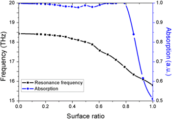
The radius of the center dish Rcenter is also an important parameter that affects cavity size in the MA. Figure 6 shows the influence of Rcenter on resonance frequency and absorption intensity. Surface ratio is the ratio of various Rcenter and initial radius of the dish as 2.7 μm, when Rcenter decreases from 2.7 μm to 0 corresponding conventional MA (surface ratio = 1) to charge cavity MA (surface ratio = 0) structure. Absorption intensity linearly increases from 0 to 100% according to surface ratio decreases from 1 to 0.8 (Rcenter = 2.4 μm) and keep up to zero of surface ratio. Resonant frequency also increases from 15.77 THz to 18.43 THz when surface ratio decreases from 1 to 0. Conspicuously, the perfect absorption is obtained not only by creating a real 'hole' but also by a minor defect (∼20% area reduction) of the center dish. This result indicates the effect of cavity on resonant frequency and absorption intensity of MA, which can be tuned via structural parameters.
Figure 6. Dependence of surface ratio on resonant frequency (squares, black) and absorption intensity (circles, blue).
Download figure:
Standard image High-resolution image
4. Conclusion
We numerically studied a cavity induced PA at the THz frequency regime of electromagnetic wave in a MAC structure. Based on magnetic field distribution, surface current and power loss density in the MA, analysis of the absorption spectra indicates that the PA peak is caused by the cavity. The absorption frequency and absorption intensity of MA can be tuned by cavity diameter or radius of the center dish whereas the absorption intensity can be either maintained at unity while shifting in a range of 2 THz or fluctuated at a certain frequency. The obtained result is an important step towards tunable MA and broadband absorption.
Acknowledgments
This work was supported by Vietnam Academy of Science and Technology (grant No. VAST 03.02/15-16).