

Abstract
In this paper interdigitated electrodes for gas sensors were fabricated by inkjet printing technology. Silver electrodes were inkjet printed on Si/SiO2 substrates instead of traditional photolithography method. The inkjet printing parameters to obtain desired dimensions, thickness of the electrodes and distance between the interdigitated electrodes were optimized in this study. The fabricated interdigitated silver electrodes were tested for application in ammonia gas sensors. Conductive polyaniline (PANI) layer was coated on the silver interdigitated electrodes by drop-coating. Ammonia detection of the PANI-coated chips was characterized with a gas measurement system in which humidity and ammonia concentrations were well-controlled. The electrical conductivity of the PANI films coated on the electrodes was measured when the PANI films were exposed to nitrogen and ammonia. The conductivity of the PANI films decreased significantly due to the deprotonation process of PANI upon ammonia expodure. The recovery time was about 15 min by heating up the polymer chip at 60 °C. The results showed that the silver electrodes fabricated by inkjet printing technique could be used as a sensor platform for ammonia detection.
Export citation and abstract BibTeX RIS

Original content from this work may be used under the terms of the Creative Commons Attribution 3.0 licence. Any further distribution of this work must maintain attribution to the author(s) and the title of the work, journal citation and DOI.
1. Introduction
Interdigitated metal electrodes are widely used for various sensor applications, such as gas sensors, humidity sensors, biosensors, and so forth [1–5]. The interdigitated electrodes are often chosen as a component for those sensing operation, where electrical signals generated by sensing materials are detected via interdigitated electrodes. Normally, the interdigitated electrodes are fabricated by photolithography. Photolithography is generally used for fabrication of micro-structures. It requires many process steps, including photoresist coating, exposure, development and etching processes, to generate patterns after thin film deposition [6–9]. Due to demand of low-cost manufacturing and shorter product development time, an alternative simple method has been proposed, especially for printed electronics applications. Inkjet printing, a direct and additive fabrication technology has recently been interested for the production of micro-patterns. Its advantages include low-cost and low-temperature microfabrication on flexible substrates, which are especially attractive for paper electronics, identification tags, as well as disposable electronic devices. Moreover, ink consumption of this technique can be reduced due to drop-on-demand process, which allows delivery of precise amount of various solution-based materials, such as nano-particle colloids, polymers, organic-semiconductors, and organo-metallics [10].
Inkjet printing technology to fabricate copper circuits on flexible polyimide substrates for electronics application was developed by Busato et al [11]. Loffredo et al [12] used inkjet printing to fabricate silver electrodes on alumina substrates and coated gas-sensitive material, which was a composite including polymer (atactic polystyrene, poly(ethylenimine)) and black carbon on electrodes. These sensors were used to measure concentrations of acetone and toluene in air at room temperature. The results were compared with those of devices whose electrodes were fabricated by conventional photolithography and the gas-sensitive materials were coated by casting and spraying techniques. Moreover, inkjet printing has been used to coat gas-sensitive materials on electrodes. Kukkola et al [13] presented inkjet printing of solid electrolyte, which was a mixture of H3PW12O40 and polyvinyl chloride to fabricate hydrogen sensors (with concentration of hydrogen below 100 ppm in air). The sensors were transistors with nano structure of metal-electrolyte-insulator-semiconductor. Mabrook et al [14] used inkjet printing to coat electrically conductive polypyrrol film to measure ethanol and methanol concentrations.
Ammonia (NH3) is a highly toxic gas with the smell of urine and it dissolves in water. Inhalation of ammonia at high level could burn respiratory and sore throat. Thus, detection of ammonia is important in industrial, medical, and environmental areas [13]. Polyaniline (PANI) is a highly versatile conducting polymer and it is suitable for various sensing applications. Sensors composed of PANI and other conducting polymers have routinely been applied to analysis of ammonia and other gases, such as a chip-based solution-cast PANI sensor [15], ammonia sensor based on a PANI dodecyl-benzene sulfonate emulsion (in chloroform) [16]. Recently, the use of a PANI-coated filter paper for a number of applications including the colorimetric detection of gaseous and aqueous ammonia has been reported [17]. PANI is an excellent material for ammonia sensing because ammonia deprotonates the amine groups of emeraldine salt PANI (ES-PANI) which is then converted to emeraldine base PANI form with a corresponding drop in conductivity of several levels of magnitude [18].
In this paper fabrication of silver interdigitated electrodes for NH3 sensors using inkjet printing technique is reported. Influence of thickness on resistance of the interdigitated electrodes, dimensions of the printed electrodes were investigated ES-PANI and ethylene glycol (EG) blend film as an NH3 sensing element was drop-coated on the silver electrodes. I–V measurements of the ES-PANI: EG blend films coated on the micro-electrodes were carried out in a controlled environment. Effect of relative humidity (RH) on resistance of the blend films and the resistance dependence of the blend films on varied NH3 concentrations at low RH was studied.
2. Experimental
2.1. Materials
Emeraldine base polyaniline (EB-PANI (Mw. 20 000), EG (99.8%), dimethylformamide (DMF) (99.8%) and HCl (37%) were supplied by Sigma Aldrich (Germany). All the chemicals were used as purchased without further purification.
Several commercial silver inks were examined for using on Dimatix DMP-2800 (FujiFilm Dimatix, Inc.) inkjet printer. Among these inks, good results could be obtained with Sunjet U5603 ink with a silver concentration of 20 wt% (Sun Chemicals, USA).
2.2. Printed electrodes
Parameters of the inkjet printing system such as voltage applied to the piezoelectric transducer and the meniscus pressure were selected towards a stable ejection of a ball-shaped droplet of the colloidal suspensions with an optimized jetting frequency at 5 kHz and the voltage applied between 16–20 V. The inkjet printing was performed with a resolution of 600 × 600 dpi on Dimatix DMP-2800 printer [10, 19]. The silicon (Si) wafers were coated with 780 nm thick SiO2 by oxidation process of Si wafers at 1100 °C for 6 h. After oxidation, the wafers were rinsed in acetone, ethanol, DI water, and then dried with nitrogen gas. The silver electrodes were printed on a SiO2/Si substrate and then annealed in a conventional oven for 4 h at 150 °C.
The electrode patterns were designed with the Corel software. The overall dimensions were 1 cm × 1 cm including the interdigitated electrodes with different dimensions of length (L), width (W) and the gap between the interdigitated electrodes (D) (figure 1). A series of electrodes with different dimensions were fabricated as shown in table 1.

Figure 1. The interdigitated electrodes with designed dimensions.
Download figure:
Standard image High-resolution imageTable 1. Designed parameters of the electrodes for inkjet printing processes.
| Sample | L (μm) | W (μm) | D (μm) |
|---|---|---|---|
| M100 | 6900 | 100 | 100 |
| M150 | 6850 | 150 | 150 |
| M250 | 6800 | 250 | 250 |
| M300 | 6750 | 300 | 300 |
| M350 | 6700 | 350 | 350 |
| M400 | 6650 | 400 | 400 |
2.3. Preparation of polymer solutions and sensor chip
2.3.1. EB-PANI solution
Mix 30 mg EB-PANI with 10 ml DMF solvent, stirring for 24 h with magnetic stirrer at room temperature (25 °C) to obtain EB-PANI solution. The solution was then filtered through filter paper. The obtained polymer solution has dark blue color.
2.3.2. ES-PANI solution
EB-PANI powder was protonated by HCl 1 M solution to obtain ES-PANI (green color). The salt was filtered and rinsed by DI water to remove residual acid. Next, ES-PANI was dried under vacuum at 60 °C in a vacuum oven. 30 mg ES-PANI was mixed with 10 ml DMF to obtain ES-PANI solution. This solution underwent ultrasonication and centrifugal mixing.
2.3.3. Blend solution of ES-PANI:EG
Mix 30 mg ES-PANI powder and 15 mg EG with 10 ml DMF solvent, stirring until ES-PANI was completely dispersed in the solution.
2.3.4. Preparation of NH3 gas sensor
The silver electrodes after fabrication were coated with the blend solution of ES-PANI:EG by drop-coating method. 4 μl of the blend solution was dropped on the silver electrodes. These polymer-coated electrodes were then heated in vacuum oven at 60 °C for 24 h to remove completely DMF solvent.
2.4. Characterization
UV–vis absorption spectroscopy of the commercial silver ink and the PANI samples was obtained from a double beam spectrophotometer Cary 100 (Varian, USA) in the wavelength range from 200 to 900 nm. The thickness and morphology of the silver electrodes and the polymer films after fabrication were characterized by a stylus profiler Dektak 6M (Veeco, USA) and optical microscope GX51 (Olympus, Japan). Transmission electron microscopy (TEM) was used to characterize particle size and shape of silver nano particles in the commercial silver ink.
2.5. I–V measurements
I–V measurements were performed with semiconductor parameter analyzer 4155C (Agilent, USA) in a home-built measurement setup (figure 2). The measurements were done at a low humidity to exclude the effect of humidity on conductivity of ES-PANI which has been well-known [20]. A polymer coated chip was mounted in a closed metal chamber with controlled low RH by purging with N2 gas during the measurements. After that, NH3 gas was inserted to the chamber with varying concentrations.

Figure 2. The experimental set-up for measurements. (1) NH3 generator, (2) measuring chamber, (3) semiconductor parameter analyzer, (4) humidity controller (5) regulator valve, (6) computer.
Download figure:
Standard image High-resolution imageThe low humidity of about 5% and temperature was measured by a PCMini52 hygrometer (Michell instruments, The Netherlands), accuracy ±2% RH and temperature ±0.2 °C. The temperature was 25 °C and RH was kept below 5% RH during I–V measurements. The polymer coated chips were put on two spring probe clips (figure 2) connected to the analyzer via coaxial cables.
Two-point DC resistance measurement was performed when the humidity in the chamber reached 5%. DC voltage (scanning from −1 V to +1 V, in 30 s, with step of 25 mV) was applied to two contact pads of the chips. The current going through the polymer layer was measured. Resistance R was calculated from the collected voltage and current in the I–V measurements, R = ΔV/ΔI.
3. Results and discussion
3.1. Characteristics of the silver ink for inkjet printing
Particle size and shape of the silver nano particles in the commercial silver ink were characterized by TEM images. The TEM images (figure 3(a)) show the particle size distribution of the silver nano particles in the commercial ink in the range of 8–32 nm.
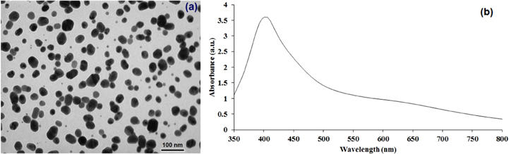
Figure 3. TEM image of the silver nanoparticles ink (a) and the UV–Vis spectrum of the ink (b).
Download figure:
Standard image High-resolution imageThe UV–Vis absorption spectra of the silver nanoparticles ink is shown in figure 3(b). The maximum of the optical absorbance appears at the wavelength of 407 nm which relates to the plasmon resonance of silver nanoparticles [21].
3.2. Influence of thickness on resistance of the printed interdigitated electrodes
Thickness of the interdigitated electrodes was controlled by changing the number of printed layers. The relationship of the resistance and thickness of interdigitated electrodes and the layer amounts is given in figure 4. In this analysis, the thickness of interdigitated electrodes layer was changed from 95 to 400 nm when the number of printed layers changed from 1 to 6. The resistance of the interdigitated electrodes rapidly decreases with increasing number of printed layers from 1 to 4 layers. The electrode thickness increases with the increase in concentration of charge carriers in the printed line, thereby resistivity of the electrode decreases. Normally, the resistance should decrease linearly with respect to the number of printed layers. Nevertheless, the results showed nonlinearity.
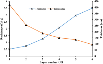
Figure 4. Effect of the printed layers on the resistance and thickness of the interdigitated electrodes.
Download figure:
Standard image High-resolution imageThis nonlinear trend can be due to different deposition volumes per layer as the number of layers increases. However, the most likely reason of this nonlinearity can be due to the presence of organic residue between the layers. The organic materials between the layers usually come from any additives in the ink other than the solvent (surfactants and viscosity modifiers) which do not evaporate completely during the sintering process of each layer [10, 19]. This can cause the slow decrease of the resistance of the electrode when increasing the number of printed layers from 4 to 6. In this study four layers (200 nm thickness) were selected to print.
3.3. Dimension of the printed electrodes
The dimensions of the electrode surfaces were studied by using Olympus GX51 microscope. Figure 5 shows the series of silver electrodes fabricated by using inkjet printing process on SiO2/Si substrate with different dimensions. Table 2 shows dimensions of the silver electrodes after printed on the Si/SiO2 substrates. The dimensions of the electrodes had a deviation in comparison to the designed dimensions. An increase in length (L) and width (W) led to a decrease in gap (G). This increase is due to spread trend of ink drop when the ink dropped on the substrate surface.
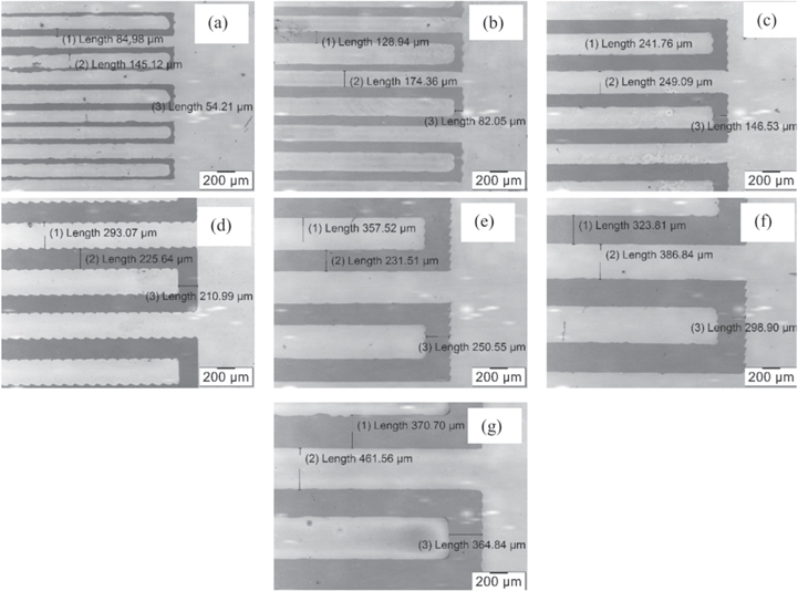
Figure 5. The images of the electrodes fabricated by inkjet printing method with different dimensions: (a) M100, (b) M150, (c) M200, (d) M250, (e) M300, (f) M350 and (g) M400.
Download figure:
Standard image High-resolution imageTable 2. Dimension of the interdigitated electrodes after printed.
| Sample | L (μm) | W (μm) | G (μm) |
|---|---|---|---|
| M100 | 6921.05 | 127.03 | 72.47 |
| M150 | 6873.12 | 186.27 | 112.04 |
| M250 | 6831.17 | 277.37 | 215.42 |
| M300 | 6785.72 | 348.61 | 241.97 |
| M350 | 6729.71 | 388.32 | 301.37 |
| M400 | 6681.04 | 447.65 | 335.04 |
The printed lines of the electrodes had trends to stick together (causing a short circuit) when the dimensions of the electrodes were smaller than the dimensions of the sample M100. Hence the optimal dimension for the interdigitated electrodes was chosen to be greater than the sample M100.
3.4. Spectroscopy of EB-PANI and ES-PANI
UV–vis spectroscopy of EB-PANI and ES-PANI was carried out with Cary 100 (Varian, US) in the wavelength range from 200 to 900 nm. UV–vis absorption spectra of EB-PANI and ES-PANI in DMF are shown in figure 6.

Figure 6. UV–vis absorption spectra of EB-PANI and ES-PANI in DMF.
Download figure:
Standard image High-resolution imageUV–vis spectrum of EB-PANI in DMF solvent shows clearly two peaks at wavelength of 325 nm (assigned to the π–π* transition of the benzenoid ring) and 640 nm due to the localized quinoid structure of EB-PANI [22–24]. The absorption of ES-PANI in DMF solvent shows three distinctive peaks appear at 325 nm (assigned to the π–π* band), 440 nm and the polaron band at 870 nm [23, 25].
3.5. Effect of electrode dimensions on resistance of the PANI:EG blend films
Resistance measurements of the ES-PANI: EG films coated on the electrodes were carried out in the closed chamber at low humidity (2.8%) to exclude the crossing effect of humidity and light on the resistance of the ES-PANI:EG films. Figure 7 shows that the resistance of the PANI chips depends strongly on the dimensions of the silver electrodes, especially the width W and the gap G. When the gap G between two interdigitated electrodes increases, the resistance of the PANI coated chips increases. This is due to the fact that the charge carriers in the PANI layer have to travel a larger distance between two interdigitated electrodes.
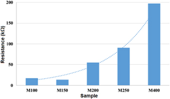
Figure 7. Effect of the electrode dimensions on resistance of the PANI:EG blend films.
Download figure:
Standard image High-resolution imageThe results also show that the chip M150 with the gap of 112 μm and thickness of about 150 nm had the lowest resistance (about 13.7 kΩ). The chip M150 was then used for gas characterizations.
3.6. Effect of RH on resistance of the polymer coated chips
The measurements were performed at room temperature in flows of N2. The humidity-controlled N2 gas was prepared by varying the mixing ratio of a dry N2 gas and a water-saturated N2 gas which was prepared by bubbling the N2 gas through DI water. Figure 8 shows the relationship between resistance of the chip M150 and RH. When the humidity inreased from 3% RH to 70% RH the resistance decreased from 87 to 25 kΩ. The increase in conductivity of the conducting polymer PANI by the absorption of water molecules is a well-known phenomenon [26–29]. This can be explained by the formation of hydrogen bondings between water molecules and either the PANI backbone itself, or with the donor molecules. The results also show only a slight change in background response from 35% to 70% RH.
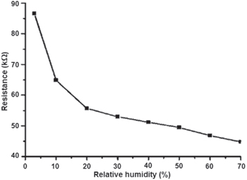
Figure 8. Effect of relative humidity on resistance of the PANI coated chip M150.
Download figure:
Standard image High-resolution image3.7. Sensor performance for ammonia (NH3) gas sensing
The measurements were carried out at room temperature (25 °C) and 5% RH. The polymer chip was stored in an airtight test chamber. The concentration of NH3 was varied by controlling the N2 gas through an NH4OH solution. When the steady resistance of the polymer chip at 5% RH had been achieved, NH3 gas was introduced into the chamber. The resistance of the polymer chip increased dramatically after the chip was exposed to NH3 gas. The resistance of the polymer chip was recorded continuously before NH3 introduction and during the time of NH3 exposure. Then the test chamber was purged with N2 gas consecutively until the resistance reached steady and kept stable.
Figure 9 shows the relationship between resistances of the polymer chip and NH3 gas concentration which varied from 0 ppm to 100 ppm. It can be observed that the resistance of the polymer chip increased in the presence of NH3 vapor. This is due to the interaction of PANI with ammonia as the following reaction [30]:

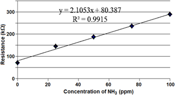
Figure 9. The relationship between resistance of the sensor and NH3 concentrations.
Download figure:
Standard image High-resolution imageAccording to equation (1), the amount of protons H+ reduces as PANI interacts with NH3. NH3 is an electron donor so it can deprotonate the ES-PANI and convert the conducting ES-PANI to the insulating EB-PANI form. So the resistance of PANI increases. The resistance of the chip varied linearly with the NH3 concentrations in the range of 0–100 ppm. It also shows that this sensor has high sensitivity in the low level of NH3 concentration and the detection limit was less than 25 ppm.
Figure 10 shows the response of the polymer chip as a function of time when the chip was exposed to NH3 and then pure N2 for 7 times (each time for 10 min) at 5% RH. It can be seen that the sensor has a good reproducibility with relatively minor deviations over seven replications. The response time was very short after the sensor was exposed to NH3 gas in the chamber.
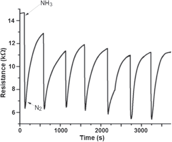
Figure 10. Sensing response of the gas sensor at room temperature.
Download figure:
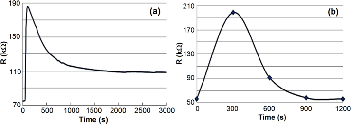
Standard image High-resolution imageFigure 11 shows recovery time of the sensor after the chip sensor was exposed to NH3 gas (50 ppm) at room temperature (25 °C), and then the chamber was purged with N2. The recovery time of the gas sensor was very long (more than 50 min) (figure 11(a)). To reduce the recovery time of the sensor, the sensor was heated at 60 °C for 10 min after exposure to NH3 gas. The recovery time of the sensor was significantly reduced from 50 to 15 min (figure 11(b)). This effect was also observed by Matsuguchi et al [31]. It could be attributed to the fact that heating at 60 °C could enhance the fast desorption of NH3 molecules out of the PANI layer.
Figure 11. The recovery time of the gas sensor at (a) room temperature (a) and (b) 60 °C.
Download figure:
Standard image High-resolution image
4. Conclusion
In conclusion, silver interdigitated electrodes were fabricated by using inkjet printing technology. The technical parameters for printing electrodes were optimized. The blend films of PANI:EG coated on the fabricated interdigitated silver electrodes exhibited good sensitivity to ammonia gas. The sensor showed a linear response to NH3 concentrations at room temperature. Fast recovery time of about 15 min could be obtained in the heat treatment of the sensor at about 60 °C. These results confirmed that the metal interdigitated electrodes fabricated by inkjet printing technique could be used as a sensor platform for ammonia detection.
Acknowledgments
The authors highly appreciate the financial support of Vietnam National University Ho Chi Minh City. This research is funded by Vietnam National University Ho Chi Minh City under grant number B2012-32-04.