

Abstract
Submerged arc discharge in liquids has shown to be a promising method to synthesize a wide variety of nanomaterials. However, it requires an accurate arc current control to ensure the desired purity and structure of the products. A fluctuating arc current increases the dispersion in size distribution, as well as in the obtained nanoparticles structure pattern. Consequently, the arc current stability is essential to ensure the product homogeneity and quality. A system which ensures high stability of the arc discharge is presented. It has three basic elements: an electrode gap micropositioning system controlled by a feedback arc current measurement, a current's stabilization element and a data acquisition system to record the magnitudes of the relevant physical parameters. The most suitable algorithm for micropositioning system was determined. The utilization of a step motor gave an additional advantage in measuring the anode displacement. The employed stabilization element improves the current and power stability by 4 and 2.7 times, respectively. The data acquisition system allows taking control and information about the relevant parameters of the process and the interaction between them. This system, based on direct arc current measurement, is superior in terms of achieving higher stability and current sensibility, to the ones based on arc voltage or arc light emission. It is also an adaptable tool to carry on further experiments.
Export citation and abstract BibTeX RIS

Original content from this work may be used under the terms of the Creative Commons Attribution 3.0 licence. Any further distribution of this work must maintain attribution to the author(s) and the title of the work, journal citation and DOI.
1. Introduction
The large-scale production of carbon nanoparticles (CNPs) still faces significant technological and economic challenges. In recent years, plasma generated in liquids has shown to be a promising method for nanoparticles synthesis [1, 2]. Although this method is simple, it still requires a careful control of the relevant parameters to ensure the desired purity and structure of the products.
In the submerged arc discharge, the arc bubble region behaves as synthesis reactors. The bubbles dimensions depend on the arc power value and determine the size of the synthesized nanoparticles [3]. A fluctuating arc current increases the dispersion in size distribution, as well as in the obtained nanoparticles structure pattern. Consequently, the arc current stability is essential to ensure the product homogeneity and quality, but to control it in liquids is a difficult task [4].
In previous works the arc discharge stability has been qualified but not quantified. Some of the reported experiments were lack of the arc current control [1–3]. Usually, articles do not mention what specific type of power supply was employed. Furthermore, the typical reported synthesis time was no longer than 2 min.
In order to control the arc discharge three main approaches have been reported: the first of them is based on arc light emission measurement (optoelectronic control), the second uses an arc voltage control and the last one relies on the arc current measurement.
The optoelectronic control has several limitations as reported in [5]. In regards to the second approach [6], according to a typical arc voltage/current characteristic, in its hissing part (where the thermal ionization is present and the nanoparticles are formed), the voltage variation is very small in comparison to its corresponding current variation ( ≈ 0), thus making less sensitive the control. On the contrary, other works use arc current as a more appropriate control parameter [7, 8].
All these types of controls act over a micropositioning mechanism using dc-servo motors [4, 6] or by means of step motors [7, 8]. The mechanism is not fast enough to quickly adjust the arc gap between submerged electrodes in order to compensate the arc current fluctuations. Therefore, the micropositioning mechanism must be complemented with an electrical stabilization element.
In the synthesis of CNPs, not only arc current but several physical parameters influence on the growth and properties of the nanostructures [6, 8]. Therefore, it is necessary to simultaneously register such parameters in order to analyze and optimize the process.
According to the previous analysis, a CNPs synthesis system based on submerged arc discharge should have three basic elements: (a) an electrode gap micropositioning system controlled by a feedback arc current measurement, (b) a current's stabilization element and (c) a data acquisition system (DAQ) to record the magnitudes of the relevant physical parameters in a correlated way. In this paper, a system that has such basic elements is reported.
2. Experimental setup
A synthesis station, composed of a DC power supply (5), a ballast resistor (1), an electronic DAQ and control system (2), a micropositioning system (3), a synthesis chamber (4) and a chilling unit (6), was built up (figure 1).

Figure 1. Schematic diagram of the setup for synthesis of carbon nanoparticles.
Download figure:
Standard image High-resolution imageAs electrodes, spectroscopic pure graphite rods were used (cathode:  , length = 20 mm; anode:
  , length = 100 mm). They were submerged to a depth of 8 cm in
  resistivity distilled water contained on a 5L double walled stainless steel synthesis chamber. Two glass windows allowed visual contact with the arc and the electrodes when aligning, testing or experimenting.
A 5 kW AC to DC power supply ( ,
,  ) was used and a
  ballast resistor was placed in series with the electrodes. An aluminum table, placed over the synthesis chamber, supports the control system, a step motor and a micropositioning mechanism. The mechanism has one axis translation car, driven by a step motor, for shifting the anode. Every step made by the mechanism is equivalent to
  . Two vertical bars hold both anode and cathode in horizontal position. The cathode is fixed while the anode is coupled to the car. Two electrical switches (limit switches), connected to the control system, sense the initial and final positions of the car. A chilling unit forces the cold water to pass inside the chamber's double wall avoiding the evaporation of the solution and consequently, keeping constant the solution's level and the arc region bubble's pressure.
An electronic DAQ and control system measures five analog correlated signals, stabilizes the arc discharge as well as interfaces with a PC.
For measuring the arc current, a shunt resistor was placed in the electric circuit in series with the electrodes (figure 2).The voltage drop over the shunt is proportional to the arc current. The voltage applied to the electrodes was measured from the anode holder disregarding the voltage drop at the shunt. The other three analog inputs are free to use for experimental purposes as in [5].
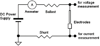
Figure 2. Electric circuit of the synthesis station.
Download figure:
Standard image High-resolution imageThe whole system is controlled by a microcontroller (PIC18F4550) that measures the analog signals by using its 10-bit ADC, counts the steps made by the motor, senses the state of the limit switches and exchanges data with a PC through a USB 2.0 interface (figure 3). A PC data acquisition software was also developed in LabVIEW8.6.
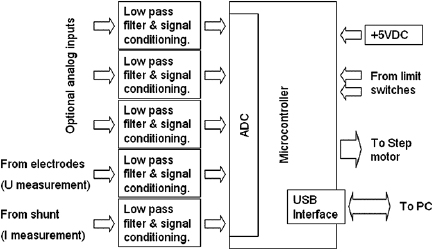
Figure 3. Block diagram of the DAQ and control system.
Download figure:
Standard image High-resolution imageAccording to the control algorithm the microcontroller measures the arc current and by comparing it with prefixed values, decides to move or not the anode towards or backwards the cathode. At the beginning, the arc current is zero, so the control system moves the anode until both electrodes made contact and the arc starts. After that, the system tries to maintain the settled current and, upon request, it transmits to a PC the recorded parameters at a sample rate of 50 samples s−1.
Three control algorithms were tested during the experiments: 'forward-backward', 'only forward' and 'constant speed'. The first two algorithms are identical, but in each case the maximum ( ) and minimum (
 ) arc current set-points are different so the resultant behaviour is not the same (figure 4). In 'forward-backward' the desirable synthesis current (
 ) was between
  and
and  set-points (
 ) making the anode to constantly move, forward or backwards, in order to get the appropriate synthesis current. In 'only forward' case, the minimum current set-point was fixed equal to the desirable synthesis current (
 ) and
) and  was taken just as an over current protection. In that way, the anode was mainly moving towards the cathode or stopped. In both cases, no movements of the anode are ever made when the arc current is between
  and
and  .
.
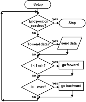
Figure 4. Flow chart of the 'forward/backward' and 'only forward' arc current control algorithms.
Download figure:
Standard image High-resolution imageIn the third control algorithm, the anode displacement speed was constant and independent from the arc current value (open loop).
The system was tested synthesizing carbon nanomaterials in water. The experiments were carried out with and without ballast resistor. In both cases, the resultant arc current stability was quantified. The obtained carbon nanomaterials were characterized by TEM (Philips EM 208–200 kV Accel Voltage) and SEM (TESCAN MIRA 3). IR spectra were acquired in a Perkin-Elmer spectrometer (FT-IR/ATR).
3. Results and discussions
Figure 5 shows the image of the installation during its operation.

Figure 5. Automated system for the synthesis of nanostructures.
Download figure:
Standard image High-resolution imageThe 'forward-backward' algorithm showed instability, sometimes causing the arc to turn off. This happened because of the changes in the motor's direction of rotation, the micropositioning mechanism's inertia and the electrode's mechanical oscillations caused by the arc discharge. In the 'constant speed' algorithm, due to the irregular anode erosion, an error on the displacement over the time is accumulated so the arc current slowly increases or decreases. The 'only forward' algorithm showed the best results in terms of arc current stability. As the electric arc constantly erodes the anode, the gap permanently increases, making backward movements not necessary. Using this algorithm, several actions were taken in order to improve and evaluate the arc stability.
The insertion of a ballast resistor improved the arc current stabilization (figures 6 and 7). However, other resistances present in the circuit (electrode, shunt and power supply internal resistances) could sometimes be the same order as the ballast resistor. As they all are in series, the total sum of them is the resultant ballast resistor. Any change in their values can affect the synthesis parameters. Furthermore, during the synthesis, the arc is consuming the anode and consequently its resistance is not constant. In our case, the used anode rod (10 cm long at the beginning of the arc discharge) had a total resistance of  , i.e. a 10% of the ballast resistor value. The shunt resistor had a value of
  , so its influence in the circuit was insignificant. It is necessary to point out that, when there is not a specially inserted ballast resistor, the other mentioned above resistors can produce spontaneous arc stabilization at unpredictable currents.
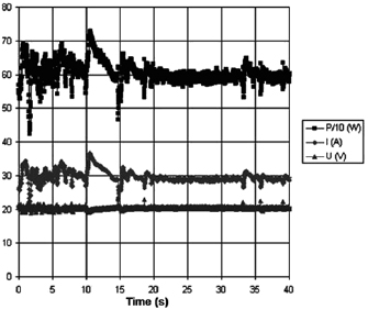
Figure 6. Electric arc power, current and voltage behavior while synthesizing in water, using 'only forward' algorithm and without ballast resistor.
Download figure:
Standard image High-resolution image
Figure 7. Electric arc power, current and voltage behavior while synthesizing in water, using 'only forward' algorithm and ballast resistor.
Download figure:
Standard image High-resolution imageFor quantifying the arc stability, five respective runs ( ) using the 'only forward' algorithm where made with and without ballast resistor (table 1). In table, the average values (Ave.) are also reported. In the first case, both arc current and power gain stability although decreasing it in voltage. However, the first two parameters are more important for the synthesis.
Table 1. Average values of voltage, current and power of the electric arc in water, with/without ballast resistor, obtained while working at the 'only forward' algorithm.
| R | Voltage (V) | Current (A) | Power (W) |
|---|---|---|---|
| Without ballast resistor | |||
| 1 |  (3%) (3%) |
 (11%) (11%) |
 (9%) (9%) |
| 2 |  (3%) (3%) |
 (9%) (9%) |
 (8%) (8%) |
| 3 |  (2%) (2%) |
 (8%) (8%) |
 (7%) (7%) |
| 4 |  (2%) (2%) |
 (7%) (7%) |
 (5%) (5%) |
| 5 |  (3%) (3%) |
 (10%) (10%) |
 (9%) (9%) |
| Ave. |  (3%) (3%) |
 (9%) (9%) |
 (8%) (8%) |
| With ballast resistor | |||
|---|---|---|---|
| 1 |  (5%) (5%) |
 (2%) (2%) |
 (4%) (4%) |
| 2 |  (5%) (5%) |
 (2%) (2%) |
 (3%) (3%) |
| 3 |  (4%) (4%) |
 (2%) (2%) |
 (2%) (2%) |
| 4 |  (4%) (4%) |
 (2%) (2%) |
 (2%) (2%) |
| 5 |  (5%) (5%) |
 (2%) (2%) |
 (3%) (3%) |
| Ave. |  (5%) (5%) |
 (2%) (2%) |
 (3%) (3%) |
Although the arc current is the most reported electric parameter, the arc power is a more appropriated one. The last governs the electrode's sublimation rate and the bubble size. The bubble size influences on the characteristics of the synthesized nanoparticles.
The use of a step motor gave the possibility to know the anode displacement at any moment, information that can be used for further analysis of yield and for the understanding of the physics behind it.
The raw material, collected from the bottom of the synthesis chamber, is mainly composed of multiwall carbon nanotubes (MWCNTs) and onion like carbons (OLCs); other carbonaceous impurities are also present (figure 8). On the other hand, the material collected from the water's surface is composed mainly of OLCs with its characteristic polyhedral shape (figure 9). Among the observed nanostructures, there are also spherical carbon nanoonions, hollow spherical carbon nanoonions, graphene, amorphous carbon, pieces of graphite and nanorods.
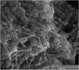
Figure 8. SEM image of the raw material collected at the bottom of the synthesis chamber, MWCNT observed.
Download figure:
Standard image High-resolution image
Figure 9. TEM image of OLCs clusters collected from the water's surface.
Download figure:
Standard image High-resolution imageThe MWCNTs were well graphitized, closed at the ends with characteristic external diameters of 12–35 nm and length in the range of 500–1500 nm and tend to be straight (figures 10 and 11). But, in some cases, the outer walls were damaged and partially covered with a thin layer of disordered material.
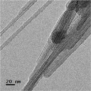
Figure 10. TEM image of MWCNT.
Download figure:
Standard image High-resolution image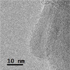
Figure 11. Image of the MWCNT tip.
Download figure:
Standard image High-resolution imageThe IR spectrum is almost flat (figure 12) and does not present absorption bands, so it can be concluded that the carbon nanostructures produced are totally or almost totally composed of equivalent  carbons.

Figure 12. IR spectrum of the synthesized MWCNTs.
Download figure:
Standard image High-resolution image
4. Conclusion
A new system for the synthesis of nanostructures based on submerged arc discharge was presented and the basic elements for such systems were described.
The use of a step motor gave an additional advantage in measuring the anode displacement, a useful means in further investigations. The 'only forward' arc current control algorithm showed the best results.
An electric stabilization element as a ballast resistor improves the current and power stability by 4 and 2.7 times respectively. Other resistors that are present in the circuit, also influence on the overall value of this element. The arc current stability was properly quantified.
The use of a data acquisition system allows taking control and information about the relevant parameters of the process and the interaction between them. It is also an adaptable tool to carry on other experiments.
The control based on direct arc current measurement is superior, in terms of achieving higher stability and current sensibility, to the ones based on arc voltage measurement or arc light emission.
To be considered in synthesis conditions, is the arc power a more appropriate parameter than the arc current.
Acknowledgments
This research work was financially supported by AENTA-Cuba (PNUOLU-7-1, 2014).The authors are indebted to H Lubian de Iraola from Department of Physics, Centro de Aplicaciones Tecnologicas y Desarrollo Nuclear, La Habana, Cuba for several valuable observations.