


Abstract
This research explains the role of NaOH and bio-activator from papaya latex in the synthesis of carbon nanoparticles from rice husks in a water medium to produce fullerene-like polytype of SiC. The process begins with the pyrolysis and then the high energy milling (HEM) process followed by dispersion of NaOH and coagulation of bio-activator. The HEM process creates residual stress which produces nanocrack. NaOH dissolved into ions which activate dipole force to create dipole moment on the tip of nanocrack and become the trigger of nanocrack dispersion. The crack dispersion breaks carbon into nanoparticles having polar electrical charge so that they are dispersed homogeneously inside the water. Bio-activator then continues to perform catalytic building molecular chain as a bridge connecting pole sides of carbon nanoparticles with the bonds of van der Walls. Catalytic performance causes the coagulation process of a nanoparticle to occur which resembles the morphological structure of fullerene-like polytype of SiC with the size of 20 up to 100 nm.
Export citation and abstract BibTeX RIS

Original content from this work may be used under the terms of the Creative Commons Attribution 3.0 licence. Any further distribution of this work must maintain attribution to the author(s) and the title of the work, journal citation and DOI.
1. Introduction
Research on nanomaterials has been rapidly developed in the field of fundamental science to investigate new and interesting phenomena. A new phenomenon is related to the high ratio of surface area to volume and effect of the size that provide the possibility for exploration of any potential application in the process of tool fabrication with nano dimension [1–7].
Material with nanostructure is the new class material having sizes less than 100 nm in its one or three dimensions. Nanostructured material is modulated on the nanometer scale in different dimensions so that it can be categorized into the structure of zero dimension (0D), one dimension (1D), two dimensions (2D) and three dimensions (3D). In short, the structure of nano 0D is a structure with all dimensions in the nanometer scale, such as quantum dots (QDs), nanoparticles, and nanospheres. The structure of nano 1D is the structure that has two dimensions in the nanometer scale, such as nanowire, nanotube, and nanobelts. The structure of nano 2D only has one size in nanoscale which is perpendicular toward the layer, such as nanoflakes, nanoplatelets, and superlattices. The structure of nano 3D formed with various entities of nanostructures such as nanowires or nanorods which are connected through the connection of single crystals and has an overall geometric dimension in nano or micro scale. Various nanomaterials (from structure 0D until 3D) have been studied and gradually introduced to industry and daily life [8].
As one of the most important semiconductor compounds, silicon carbide (SiC) has shown an extraordinary characteristic such as wide band gap, high strength, high thermal conductivity, good shock thermal resistance, low thermal expansion, and an excellent chemical inertness [9, 10]. The unique characteristics of SiC make it as an ideal candidate for power electronics, electronics for hostile environment, diodes of blue light transilluminator, sensor, composite and supported heterogeneous catalysts [11–19]. With low dimension, the presence of quantum effect and shape effect, nanostructure is expected to be able to show characteristics which might not be possessed by most of other semiconductor materials. Intensive research has been focused on the synthesis or fabrication of the SiC nanocarbon structure and to connect its morphology with mechanical, optical and electrical, sensory behaviors etc [20–24].
Various efforts have been made to explore the characteristics of nanocarbon structure of SiC starting from numerical modeling to experimental research. Several numerical modeling have been conducted to observe, such as the relation of graphite and tubular shapes of SiC nanocarbon with optical characteristics and emission absorption [25]. Ab initio modeling on structure stability and electrical character of a fullerene-like cage (SiC)12 and its product derivative has also been published [26]. Meanwhile, Goudarziafshar et al [27] conducted computation to figure out the absorptivity of hydrogen in the nanostructure of silicon carbide fullerene (SiC)16.
Experimentally, various methods have been developed in the synthesis of SiC nanocarbon depending on the desired material structure (powder, ceramic, single crystal etc) [28]. A conventional approach widely used for powder synthesis is known as the Acheson process. In that case, reduction of SiO2 by C to form SiC nanocarbon is made approximately at 2500 °C. Another method for large scale production of SiC used the reaction between Si and C with medium enthalpy change (−73 kJ mol−1) [29]. This reaction is characterized as combustion synthesis or self-propagating high-temperature synthesis (SHS) [30].
Besides the conventional approach, material for SiC nanocarbon can also be synthesized by different non-conventional methods such as laser-assisted chemical vapor deposition (CVD) [31], modified CVD method [32], method of change from sol to gel using tetraethyl orthosilicate (TEOS) [33–35], and catalyst assisted method [36]. Compared to the conventional approach, the non-conventional one can produce better products with higher purity level at a relatively lower temperature process. Nevertheless, several weaknesses for the non-conventional approach are high cost and highly complicated tool installation. Besides that, a precursor used in the non-conventional approach is usually harmful to the environment. On the other side, Acheson method also has its negative side since it requires heating at a very high temperature (the maximum temperature may reach 2700 °C) because of the less contact between reactant as a result of the big size of particles.
To complement this issue, researchers have been attempting to use finer initial material to increase contacts between reactant. One of the possible initial materials is agricultural waste or plant-based biomass. This plant-based biomass contains cellulose components that can be easily converted into carbon (C) and a huge amount of silica (SiO2) on the epidermis absorbed during the regeneration of cell wall [37]. Several plant wastes that have been known for containing SiO2 are rice husks, straw, sugarcane leaves and coconut shell [38]. Some researchers report that a variety of plant extracts can be used as bio-activator in the synthesis of several types of metals into nanoparticles [39]. Other research reports that the extract of papaya callus can be used to synthesize silver nanoparticles [40]. The research shows that bio-activator in papaya latex can reduce silver nitrate solution into silver nanoparticles and reduce carbonyl in carbon charcoal to become porous carbon. Meanwhile, papaya latex can also increase the yield of carbon nanoparticles from the material of coconut shell processed with ball mill [41].
Nowadays, synthesis of carbon nanoparticles of SiC that comes from biomass waste material such as rice husks, straw or sugarcane leaves has been done [42–45]. Those various synthesis processes dominantly use the conventional approach which requires heating at a high temperature. Meanwhile, it is complicated to find a synthesis process of carbon nanoparticles of SiC which combines the use of material from plants with natural active substance or bio-activator. There is the gap that requires further studies. Therefore, the research on the synthesis of carbon nanoparticles of SiC, especially the one from rice husk waste, using bio-activator from papaya latex is essential to conduct in an attempt to develop the new method for the synthesis of carbon nanomaterial of SiC which is more energy saving and environmentally friendly. The current research fulfills the gap by studying the synthesis process of carbon nanoparticles of SiC-based on carbon charcoal from rice husks. The natural material used in this research is charcoal from rice husks combined with natural active substance from papaya latex and precursor of NaOH. Papaya latex is used because it contains papain enzyme proved to be able to reduce silver nitrate solution into silver nanoparticles [40]. Meanwhile, NaOH is used since it can dissolve the functional group of alkyl halide on the carbon surface into primary amino following Gabriel reaction [46].
2. Research methods
2.1. Material preparation
A procedure for preparing material is schematically presented in figure 1. The process began with the pyrolysis of rice husks that result in the charcoal of rice husks (C-RHs). The second process was pounding the C-RHs in a stainless-steel tube using a steel ball for 2 million cycles. The third process was separating the big and the small sizes of C-RHs particles by depositing the charcoal into water in a tube, then stirred well and left for 8 h. The small C-RHs were obtained by taken off the sedimentation while the residual left in the water and the small particles of CP-RHs were then dried out.

Figure 1. The procedure for material preparation.
Download figure:
Standard image High-resolution image2.2. Dissolution and coagulation
The next process was the dissolution of CPs-RHs. One gram of CPs-RHs was reacted with 3 mol of sodium hydroxide in water for 2 h. After CPs-RHs dissolved in water, then the coagulation process was made with bio-activator from papaya latex. Bio-activator from papaya latex sediments carbon that has been dissolved and produced carbon nanoparticles of rice husks (CNPs-RHs).
2.3. Determining the physical, chemical and morphological characteristics
The determination of physical, chemical and morphological characteristics of the material from the results of the preparation was done by undertaking a set of tests such as x-ray diffraction (XRD), energy dispersive x-ray spectroscopy (EDX), Fourier transform infrared spectroscopy (FTIR), scanning electron microscope (SEM), and transmission electron microscopy (TEM). TEM, SEM, and EDX are needed to analyze sizes, shapes, and distribution of phase and chemical composition. The machine for TEM test is GEOL JEM-1400, while that for SEM is FEI inspect S-50. XRD test is required to identify the composition of surface phase or surface of CPs-RHs and CNPs-RHs, a XRD test machine is PANalytical X'PertPRO. FTIR is used to determine the name of the group or chemical bonds on the surface of CPs-RHs and CNPs-RHs, a FTIR test machine is Shimadzu.
3. Results and discussion
3.1. Phase form and surface group
The results of XRD and FTIR test on CPs-RHs and CNPs-RHs are shown in table 1 and figure 2. The XRD test on CPs-RHs results in the crystalline value of CaC2O4. H2O that is of 15.4% (see table 1 and figure 2(C1)) and XRD test on CNPs-RHs results in the crystalline value of CaCO3 that is of 13.0% (see table 1 and figure 2(C2)). Meanwhile, the residual has groups in form of the amorphous phase. Thus, it can be assumed that CNPs-RHs from the results of the process are amorphous-shaped.
Table 1. The analysis result of XRD test.
| Sample | Area under the curve | Percentage crystallin (%) | Phase crystallin | ||
|---|---|---|---|---|---|
| Crystallin | Amorph | Total | |||
| CPs-RHs | 336 | 1842 | 2178 | 15.4 | CaC2O4 · H2O |
| CNPs-RHs | 144 | 960 | 1104 | 13.0 | CaCO3 |
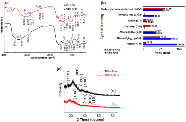
Figure 2. The result of FTIR and XRD test: (a) FTIR spectra, (b) peak areas of different bondings, (c) XRD spectra.
Download figure:
Standard image High-resolution imageBonds or groups that lie on the carbon surface are a carbonyl, carboxyl, lactone, phenol, ether, carbonyl, anhydride [47]. The result of FTIR test in figure 2(a) shows that the bond form or groups on the surface of CPs-RHs are amine (C-N), aromatic ring (C-Car), carboxyl/ether/alcohol (C-O), alkene (C-H), alkane (C-H) and phenol (O-H) (curve a1 in figure 2(a)). Meanwhile, groups on the surface of CNPs-RHs are amine (C-N), carboxyl/ether/alcohol (C-O), carboxyl (O-H), alkene (C-H), an alkane (C-H) and phenol (O-H) as shown in curve a2 of figure 2(a).
NaOH in water has a highly significant role in the dispersion of molecular groups on the surface of carbon particles. It can be seen from figure 2(b) that there was a change of peak area on several functional groups. Aromatic ring (C-Car) groups on CPs-RHs after the process are invisible on CNPs-RHs. Carboxylate groups (O-H) that were initially invisible on CPs-RHs became visible on CNPs-RHs. Peak area of the amine group (C-N), alkene (C-H), an alkane (C-H) and phenol (O-H) decreased significantly, but on carboxyl/ether/alcohol groups (C-O) there was an increase. The amount of value change of peak area on amine group is −2.701, alkene group is −5.580, alkane group is −48.197 and phenol group (O-H) is −134.043.
The change of group is caused by ion of Na+ and OH− inside the solution during dispersion process of CPs-RHs into CNPs-RHs as in figure 2(b), showing that there was a phenomenon of peak area difference on the carbon surface groups on CPs-RHs and CNPs-RHs. The phenomenon of peak area change is illustrated in figure 3. The peak area of the aromatic ring (C-Car) on CPs-RHs was invisible when turning into CNPs-RHs, while the peak area of phenol groups on CPs-RHs decreased drastically. The process of peak area change suggested in figure 3(a) occurred with the opening of double bonds on carbon by hydroxyl ions of OH−. The opening of double bonds causes the carbon to bind hydroxyl ions to form phenol group. The final step is sodium ions of Na+ got closer to the phenol group stimulating hydrogen to be released to form hydrogen ions of H+ and finally O−Na+ bond. This bond gives polar characteristic to the carbon surface.

Figure 3. Illustration of group change of CNPs-RHs surface into polar (a) aromatic ring, (b) amine, (c) alkane, (d) alkene and (e) ether.
Download figure:
Standard image High-resolution imageSynthesis shows the occurrence of amine reaction with sodium hydroxide [46]. The mechanism of the change in amine group on the carbon surface by sodium hydroxide in water is shown in figure 3(b). Hydroxyl ions of OH− stimulated N bond so that the bond got released and resulted in 2H+ to form bond with the N. The alkane change on carbon surface by sodium hydroxide is shown in figure 3(c). Hydroxyl ions of OH− stimulated hydrogen in CH3 to form Phenol and H+, then natrium ions of Na+ stimulated hydrogen in Phenol so that the surface became polar and created H+. The mechanism of sodium hydroxide changing alkene group on carbon surface is shown in figure 3(d). Hydroxyl ions of OH− opened the double bonds to form phenol, then, ion Na+ stimulated hydrogen until released to create H+ which caused the group to become polar. The change of ether group is shown in figure 3(e). Hydroxyl ions of OH− followed by ion Na+ stimulated R+ to form HO-R' so that the carbon surface became polar.
3.2. Morphology and dissolution
3.2.1. Morphology of CNPs-RHs from the results of dissolution.
Figure 4 explains the result of SEM and EDX test on CPs-RHs and CNPs-RHs. Carbon particles of rice husks which are produced from milling process with steel ball are shown in SEM photograph in figure 4(a) and the result of EDX test in figure 4(b). From figure 4(a), it can be seen that the particle size of CPs-RHs is still in micron scale. Cracks in nanometer scale which are created on carbon surface are illustrated as nanocrack. The chemical elements that are contained in the carbon can be seen in figure 4(b). Figures 4(c) and (e) are results of SEM and EDX test on CNPs-RHs which are results from the corrosion of CPs-RHs with sodium hydroxide which are then sedimented using bio-activator.

Figure 4. The results of SEM and EDX images. (a) SEM image of CPs-RHs, (b) EDX image of CPs-RHs, (c) SEM image of CNPs-RHs, (d) EDX image of CNPs-RHs, and (e) the comparisons of the percentage of chemical compositions in CPs-RHs and CNPs-RHs.
Download figure:
Standard image High-resolution imageFrom figure 4(c), it can be seen that the size of CNPs-RHs is varied between 20-100 nm. The role of sodium hydroxide as carbon disperser affects the percentage number of chemical elements in carbon as shown in figure 4(e). In CNPs-RHs, there was an increase of C, O, and Si, while Ca element decreased. The contents of Al, K, and Fe that were initially in CPs-RHs did not appear again in CNPs-RHs. Elements of Al and Fe reacted with sodium hydroxide in water turning into Al(OH)4 and Na2[Fe(OH)4]. The elements of Ca and K turned into CaOH and KOH. After being washed with water, the elements of Al, K, Fe and some part of Ca were detached from (CPs-RHs) so that they became invisible in CNPs-RHs which caused the percentage increase on the elements of C, O, and Si due to the loss of Al, Fe, and K element. The increase of Mg element came from the Mg element that was in bio-activator. The result of TEM test on CNPs-RHs from the results of dispersion of sodium hydroxide is processed using ImageJ as shown in figure 5(a). CNPs in an image with a scale of 200 nm in figure 5(a1) are shaped in granules with a variation of sizes between 20–100 nm. CNPs morphology in an image with the scale of 20 nm in figure 5(a2) is seen as little granules which resemble balls connected to other balls. The balls are made obvious in figure 5(a3) as the size less than 2 nm.

Figure 5. Morphological image of CNPs-RHs as the dispersion result of sodium hydroxide: (a) TEM image of CNPs-RHs, (b) illustrated image of the morphology of CNPs-RHs.
Download figure:
Standard image High-resolution imageIn figure 5(a3), transparent granules are visible in a very small size. The image is made obvious using ImageJ. The result is shown in figure 5(b1). From the image processing, ball morphology is obtained in which it consists of very small particles resembling molecules where the image is made obvious in figure 5(b1.1). According to the result of EDX test, the dominant chemical composition is silica Si and carbon C as shown in figure 4(e). Therefore, the morphology of CNPs-RHs in figure 5(b1) can be illustrated as a SiC composite consisting of polytypes [48, 49]. The morphology of Si and C is shown in figure 5(b1.1) which can be explained from the color. The white color is Si, and the red color is C according to the composition of SiC consisting of polytypes. The shape resembles the ball as if the shape of fullerene. Based on this elaboration, the result of the study on the morphology of CNPs-RHs is that composite SiC resembles fullerene [50–52] in which the morphology is illustrated in figure 5(b2).
3.2.2. Carbon dissolution.
The result of the SEM test in figure 4(a) and illustration of the morphology of CNPs-RHs in TEM test in figure 5(b2) shows the existence of cracks. Cracks usually occur because the dispersion process of CPs-RHs uses alkali and they are initiated by the formation of Na+ and OH− ions with sodium hydroxide in water that releases heat energy. These ions enter the cracks that size in nanocrack in which in the location of nanocrack, excitation of electron might happen as a result of residual stress formed because of the collision of steel balls. The illustration of the dissolution process is shown in figure 6.
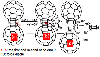
Figure 6. Illustrated image of the dissolution of CPs-RHs in the location of nano crack.
Download figure:
Standard image High-resolution imageFigure 6(a) explains the initial process of ion Na+ and OH− entering the location of electron excitation. Ion OH− stimulated electron so that the bond was open to forming phenol bond in carbon and ion Na+ was alongside the phenol. Furthermore, Na+ ion stimulated hydrogen in phenol group to produce H+, and on the carbon surface, C-O-Na+ which is polar was formed. The carbon surface that is polar gave dipole force (FD) and dipole moment (MD) [53]. Force and moment dipole create new stress in bonds between carbons. As a result, a decrease of energy of electron bonds causes crack dispersion so that current electron excitation is created as shown in figure 6(b). This reaction continued until the ball connection was broken as shown in figure 6(c). The result was the former connection created a polar surface. The surface of the broken connection had a powerful polar characteristic so that dipole force occurred between pieces of nanoparticles which resulted in a constant motion of CNPs-RHs in the water, a phenomenon that makes it difficult for sedimentation to take place in water. Therefore, NaOH in solution does have a role to open nanocrack and help the dispersion process so that the polar carbon nanoparticles can be produced. Since it is polar, the particle does not sediment due to the interaction force with the water molecule.
3.3. Morphology of CNPs and coagulation
3.3.1. Morphology of CNPs-RHs in the coagulation result.
The result of the TEM test on CNPs-RHs from coagulation result is processed using ImageJ as shown in figure 7(a). The size of CNPs according to the image with the scale of 200 nm in figure 7(a1) is varied in its granule forms which is between 20-100 nm. The morphology of CNPs in an image with the scale of 20 nm in figure 7(a2) shows the small granules resembling balls connected to other balls. These balls are made obvious in figure 7(a3) which sizes less than 2 nm. In figure 7(a3), transparent granules are seen in a very small size. The figure is made obvious using ImageJ and the result is shown in figure 7(b1). In the figure, it is shown that the morphology of CNPs-RHs balls consists of very small particles resembling molecule and the figure is made obvious in figure 7(b1.1). Based on this elaboration, then the morphology of CNPs-RHs is illustrated as resembling fullerene [50, 52–54] so that the morphology is as illustrated in figure 7(b2).
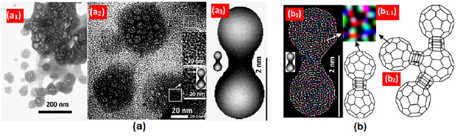
Figure 7. The morphological images of CNPs-RHs that is from the coagulation result of bio-activator: (a) TEM image on CNPs-RHs, and (b) illustrated image of the morphology of CNPs-RHs.
Download figure:
Standard image High-resolution image3.3.2. Coagulation of CNPs-RHs by bio-activator.
The presence of bio-activator in the dispersion solution of carbon nanoparticles played a role in performing the catalytic performance which connects the polar sides of carbon nanoparticles with van der Walls bonds. As a result, a bridge connecting each particle was formed. It can be seen from figure 7(a2) that two surface shapes are coarse, for the one looking dark, and fine, for the one looking bright. The dark part is the dispersed carbon nanoparticles while the bright part is the group of bio-activator that has bonded particles of aromatic group and groups from the results of decomposition by NaOH, as can be seen in figure 3. The series of groups then create bridges that connect fullerene-like particles.
The phenomenon is illustrated as the result of the coagulation process as shown in figure 8(a), the notation (a1) as CNPs-RHs which is coarse and index (a2) as CNPs-RHs which is fine. In figure 8, index (a2) is an illustration of connecting area of CNPs-RHs which is coarse. This image is then processed again to be figure 8(b). In figure 8(b), index (a2.1) is illustrated as residual bio-activator and index (a2.2) is illustrated as fine CNPs-RHs which relates to one another by bio-activator. This connection phenomenon is a change of CNPs-RHs that is polar into non-polar so that the CNPs-RHs can sediment. The process stages of the phenomenon of coagulation reaction by bio-activator are illustrated in figure 9.

Figure 8. The illustration of coagulation phenomenon. Image of TEM on CNPs-RHs in bio-activator. (a) Image of coagulation of CNPs-RHs in bio-activator. (b) The illustration of separation of bio-activator and CNPs-RHs from the image of TEM.
Download figure:
Standard image High-resolution image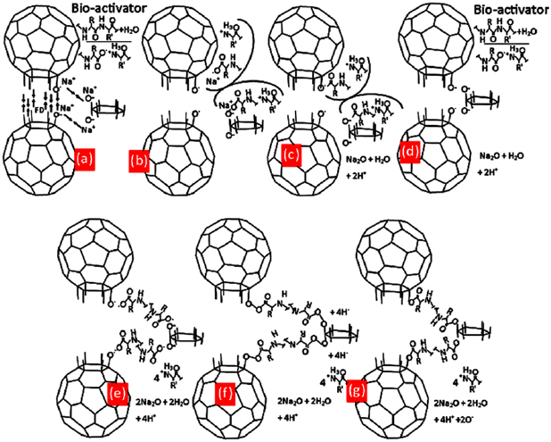
Figure 9. Illustrated image of coagulation reaction of CNPs-RHs in water. (a) First stage ionization of bio-activator, (b) depolarization of carbon surface, (c) deionization bio-activator and first product, (d) second stage ionization of bio-activator, (e)−(g) the formation of molecular chains.
Download figure:
Standard image High-resolution image
In figure 9(a), bio-activator from papaya latex [55] in water creates bio(−)-ion and bio(+)-ion [56, 57]. Bio negative ion stimulated Na+ and released oxygen O as shown in figure 9(b) which then produced carbonyl group and Na2O then formed bio-activator again by stimulating hydrogen in bio(−)-ion until it got released to produce 2H+ as shown in figure 9(c). The next step is that bio-activator in water created bio ion again as shown in figure 9(d). In figure 9(e), bio(−)-ion releases oxygen to create bonds with carbonyl so that bonds as in figure 9(f) are created and figure 9(g) is the result of coagulation of CNPs-RHs after being dried out. The illustration of this phenomenon caused CNPs-RHs to become non-polar so that it could sediment. Based on the elaboration, it can be stated that bio-activator plays a highly important role in doing a catalytic performance to build molecular chain as a bridge connecting polar sides of carbon nanoparticles with van der Walls bonds in the coagulation process of dispersed nanoparticles so that sedimentation is easily formed. This process is the excellence of the synthesis of carbon nanoparticles under the condition of room temperature so that it efficiently saves energy. The result of this process is the structure of nanoparticles of fullerene-like polytypes of SiC with a size between 20 and 100 nm. This kind of structure is the high potential to be developed as a semiconductor application, a coating on a component of radiation, sensor, and optic material [20–22, 24].
4. Conclusions
NaOH in this research had a very significant role in breaking the carbon group by forming dipole moment that could accelerate the dissolution of nanocrack so that polar nanoparticles dispersed in water are formed. Meanwhile, bio-activator of papaya latex played a role in the coagulation process of the nanoparticles so that it could easily sediment. Therefore, the synthesis process of nanoparticle from rice husks could occur at room temperature so that it can be very potential to be developed as a method that is cheap, effective and efficient. The whole process worked simultaneously and created nanoparticles of fullerene-like polytypes of SiC in the size that is between 20 and 100 nm. The material with such structure is very potential to be developed as a semiconductor application, a coating on the component of radiation, sensor and optic material.
Acknowledgments
The author would like to thank the Ministry of Research, Technology, and Higher Education of the Republic of Indonesia for financial support through PDD research scheme with contract number: 42/E/KPT/2017.